To design a high-Q Schumann resonator tuned to the fundamental frequency of approximately 7.83 Hz, we'll leverage principles from established Schumann resonance (SR) receiver designs and resonant circuits. This resonator uses a magnetic induction coil as the antenna structure, wound with thick copper antenna wire to minimize resistance and achieve a high quality factor (Q). The coil serves as the inductor (L) in an LC resonant circuit, paired with an external tuning capacitor (C) to set the resonance frequency. This approach draws from portable SR antennas with mumetal cores for enhanced sensitivity and the patent-inspired resonant transformers for ELF energy coupling. The high-Q design minimizes losses, making it suitable for detecting or potentially transducing weak SR signals, though power output remains minimal due to the low energy density of SR fields.
Design Overview
- Antenna Structure: A solenoid coil acting as a magnetic loop antenna, sensitive to the magnetic component of SR waves. The coil is wound on a high-permeability mumetal core to amplify inductance without excessive size.
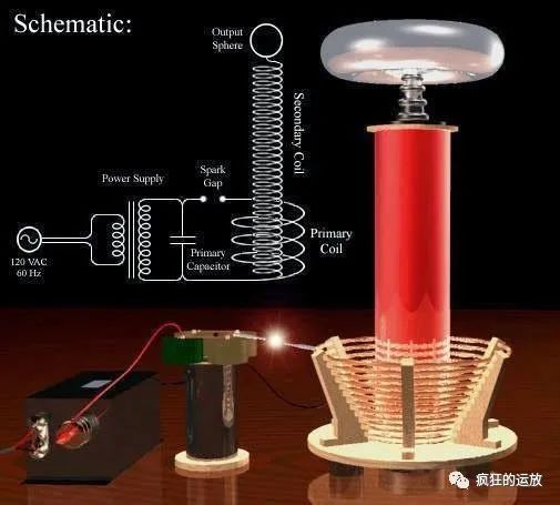
- LC Resonant Circuit: The coil provides L, tuned with a parallel or series capacitor C to resonate at 7.83 Hz. For energy transduction, couple the output to a rectifier or load, similar to Tesla-inspired resonant transformers.
- High-Q Features: Thick antenna wire reduces ohmic resistance; high effective permeability (μ_app ≈ 66) boosts L; shielding minimizes external interference. Calculated Q ≈ 66, which is relatively high for ELF circuits where damping is inherent.
- Materials:
- Core: Mumetal rod (ASTM A753 Alloy 4, relative permeability ~2 × 10^5).
- Wire: Copper antenna wire (e.g., 18 AWG, 1 mm diameter) for low resistance.
- Housing: Wooden or Plexiglas box with copper sheet shielding to reduce electrostatic noise.
- Orientation: Align North-South for optimal SR detection, as magnetic fields are horizontal.
Specifications
Using core dimensions and wire from refined calculations (adjusted for practicality with fewer turns to accommodate thicker wire while maintaining high L):
| Parameter | Value | Description |
|---|---|---|
| Resonance Frequency (f) | 7.83 Hz | Fundamental Schumann mode. |
| Core Length | 0.3 m | Standard for portable designs. |
| Core Diameter | 0.025 m | Provides length-to-diameter ratio m ≈ 12 for demagnetization factor N_d ≈ 0.015. |
| Effective Permeability (μ_app) | ~66 | Reduced from intrinsic μ_r due to open rod geometry. |
| Number of Turns (N) | 20,000 | Balanced for high L and manageable size; wound in multiple layers. |
| Wire Diameter | 1 mm (18 AWG) | Thicker "antenna wire" to lower resistance (ρ_cu = 1.68 × 10^{-8} Ω·m). |
| Inductance (L) | ~54 H | Calculated via L ≈ μ_0 μ_app N² A / l_core (A = core cross-section). |
| Resistance (R) | ~40 Ω | From wire length (~1885 m assuming average winding radius 0.015 m). |
| Q-Factor | ~66 | Q = ω L / R (ω = 2πf); high for ELF, enabling sharp resonance. |
| Tuning Capacitor (C) | ~7.6 μF | Low-loss film capacitor; C = 1 / (ω² L) for resonance. |
| Self-Resonance Frequency | >200 Hz | Ensured by low parasitic capacitance (~pF range); well above SR band. |
| Weight (approx.) | ~1-2 kg | Portable, similar to receiver designs. |
Construction Steps
- Prepare the Core: Use a 30 cm × 2.5 cm mumetal rod. Secure it in the housing with foam supports to prevent movement.
- Wind the Coil: Wind 20,000 turns of 1 mm copper wire evenly over ~70-90% of the core length (e.g., 25 cm winding length). Use multi-layer winding to fit turns compactly; aim for low inter-winding capacitance.
- Add Shielding: Enclose in a box with copper foil shielding, grounded to minimize noise. Leave terminals for connecting the capacitor and output.
- Tune the LC Circuit: Connect a 7.6 μF capacitor in parallel with the coil for a tank circuit. Use a signal generator and oscilloscope to fine-tune (adjust C slightly for exact 7.83 Hz resonance).
- Coupling for Transduction: For energy extraction, add a secondary pickup coil (e.g., 100 turns) wound over the primary, connected to a bridge rectifier and filter capacitor (e.g., 1000 μF). Initiate resonance with a brief high-voltage impulse (~10-40 kV spark gap) to couple SR fields, as in the patent.
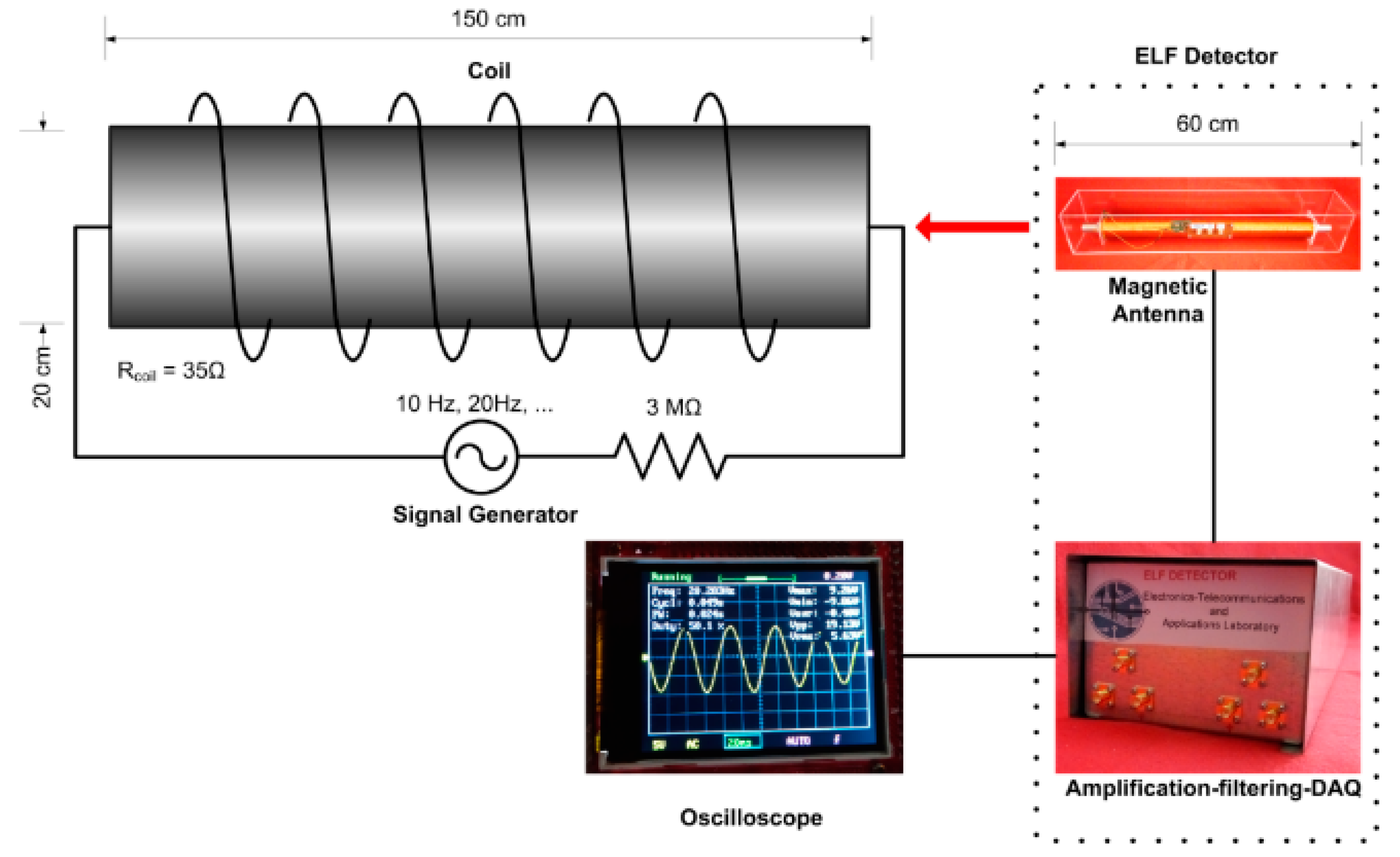
- Testing: Place in a low-noise environment; monitor voltage across the capacitor with a high-impedance probe. Calibrate using a test solenoid coil (e.g., 150 cm long, 20 cm dia, 150 turns) to simulate SR fields.
This design achieves a high Q by optimizing the L/R ratio through the mumetal core and thick wire, reducing thermal noise and losses. While effective for resonance, actual energy transduction from SR is limited to micro- or nanowatts due to weak fields (~pT magnetic, mV/m electric). For higher modes (e.g., 14.3 Hz), scale C inversely with f². If building, source mumetal from suppliers like Magnetic Shield Corp. and ensure safety with high-voltage components.
No comments:
Post a Comment
Watch the water = Lake 👩 🌊🦆